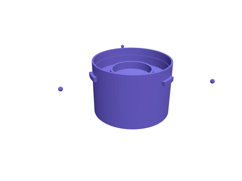
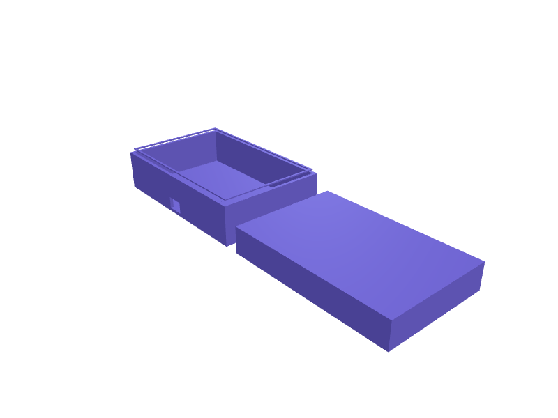
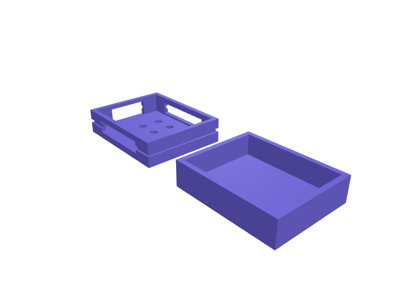
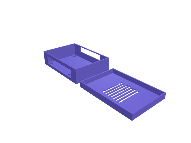
Use case
Generate custom electronics enclosures and project boxes
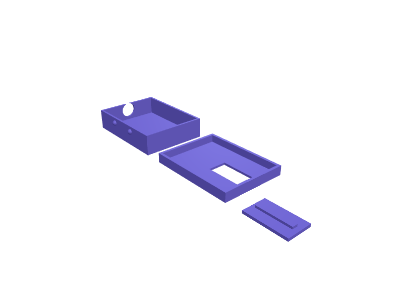
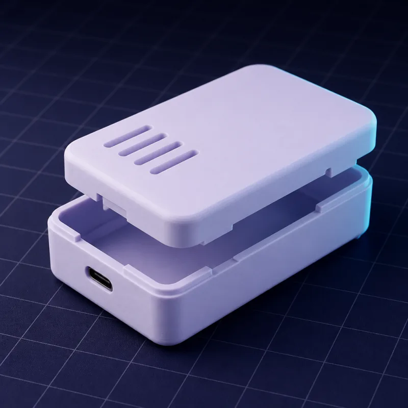
Every electronics project ends with the same chore: a box. Parametric enclosure generators exist, but they stop at a rectangle. SpeakCAD lets you describe the board, the ports, the vents and how the lid closes, then refine it by chat.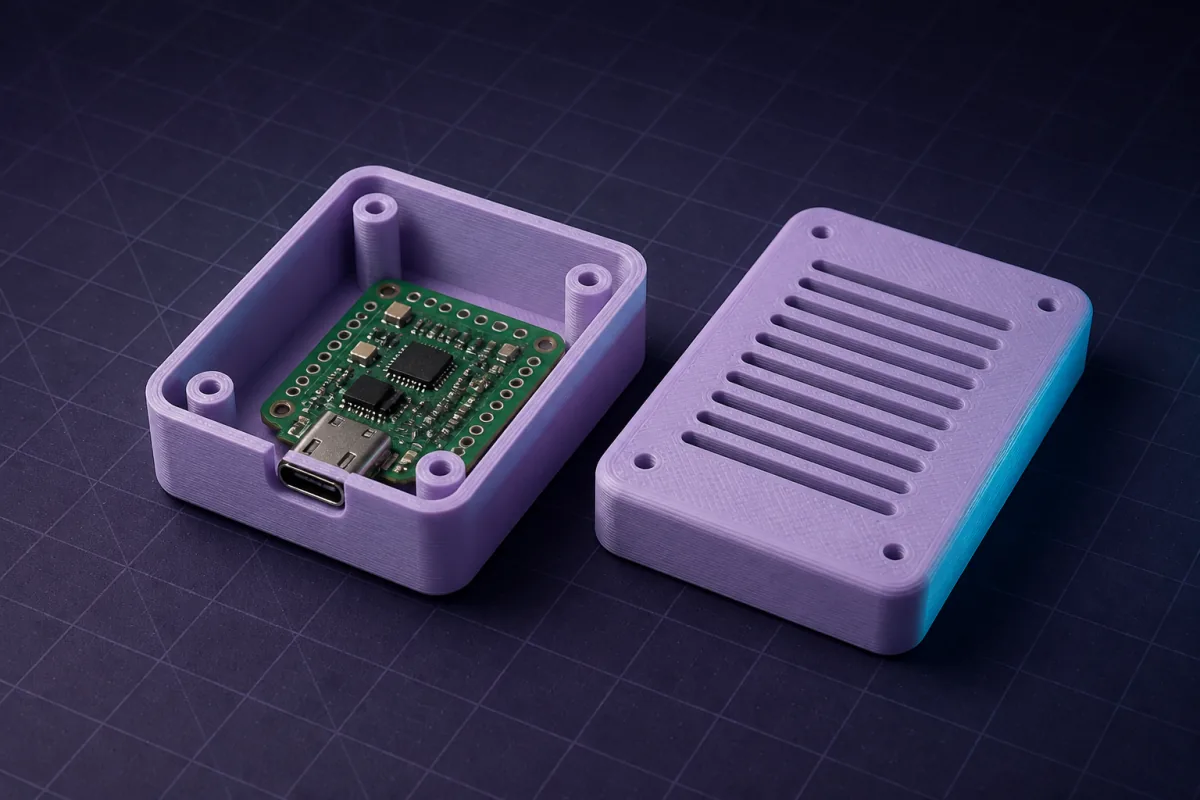
Prompts that work
Copy one into the box above and change the numbers to yours. The first render usually appears within a minute or two.“A two-part enclosure for a 65 x 30 mm PCB with 2.5 mm mounting holes 3 mm from each corner, 12 mm internal height, snap-fit lid, USB-C cutout centred on one short side.”
“A Raspberry Pi 4 case with a 30 mm fan grille on top, slots for the GPIO ribbon, and wall mount keyholes on the back.”
“A sensor box for outdoor use: 60 x 40 x 25 mm inside, 2.4 mm walls, lid with a groove for a 2 mm O-ring, PG7 cable gland hole.”
Ready-made enclosures you can open free
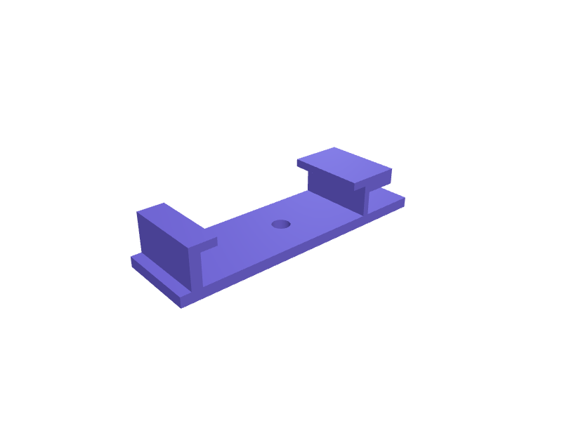
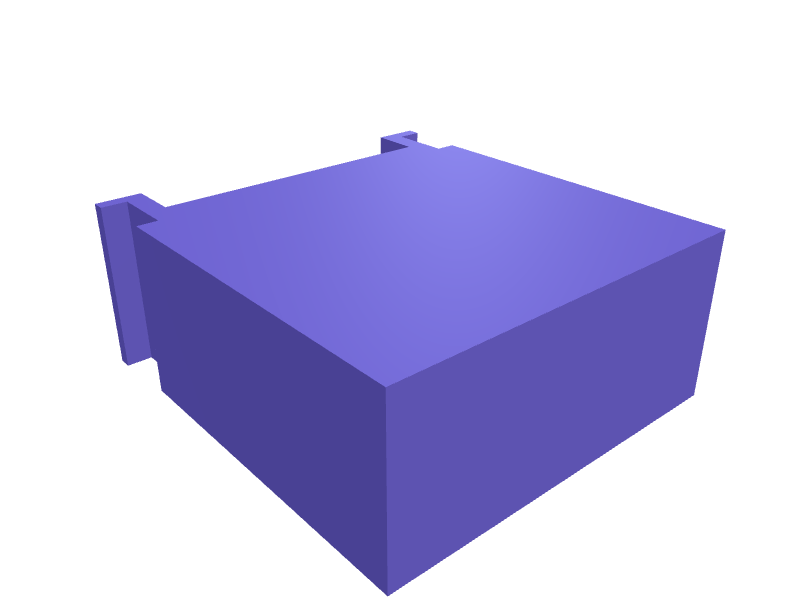
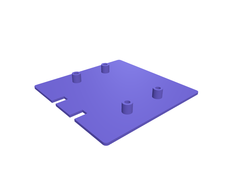
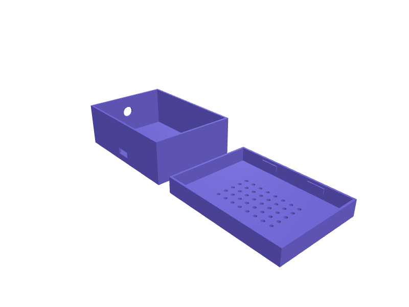
These parts already have a model. Open one in a free account, no card: turn it in 3D and change its numbers in the viewer, then download the STL or 3MF free. AI changes use credits.All enclosures & cases parts in the library →
What makes a good enclosure prompt
Give the internal dimensions (or the PCB dimensions plus clearance), the wall thickness you want, how the lid attaches, and where the openings are. Describe port positions relative to a corner or centre; the AI places them exactly.
Lid styles SpeakCAD knows
- Snap-fit lid with cantilever clips, tuned to 0.2 mm interference for PLA/PETG.
- Screwed lid with corner pillars sized for M2.5 or M3 screws, or heat-set inserts.
- Sliding lid running in side grooves, ideal for battery compartments.
- Friction lid with a 0.3 mm clearance lip for boxes opened often.
Standoffs, grilles and cutouts
Ask for PCB standoffs at your hole coordinates, honeycomb or slot vent grilles, LED light pipes, button holes, display windows and cable glands. Each is a parameter you can move later: "shift the USB cutout 3 mm to the left" is a single message.
Printability built in
Enclosures print best with the open face up and walls at least 1.6 mm for rigidity. SpeakCAD orients the shell and lid flat on the bed, adds chamfers on the bottom edges to fight elephant's foot, and keeps clip geometry within FDM tolerances.
Board sizes and hole patterns
The numbers below come from our board-by-board enclosure guides. "Inner size" is the clearance around the board and the internal height those guides use; measure your own board revision before printing, because clones and new revisions move holes and ports.
| Board | PCB (mm) | Mounting holes | Screw | Suggested inner size | Guide |
|---|---|---|---|---|---|
| Raspberry Pi 5 | 85 x 56 | 4 x 2.7 mm on 58 x 49 mm, 3.5 mm from the edges | M2.5 standoffs, 3 mm tall | 0.5 mm clearance, 24 mm tall with the Active Cooler (lid open 60 x 40 mm above it) | Pi 4 and Pi 5 case |
| Raspberry Pi 4 Model B | 85 x 56 | Same as the Pi 5 | M2.5 standoffs | 0.5 mm clearance, 20 mm tall (vented, 30 mm fan grille in the lid) | Pi 4 and Pi 5 case |
| Raspberry Pi Zero 2 W | 65 x 30 | 4 x 2.75 mm on 58 x 23 mm, 3.5 mm from the edges | 2.5 mm locating pegs, or M2.5 into 4 mm standoffs | 0.5 mm clearance, 9 mm tall (12 mm with a soldered header); outside about 70 x 35 x 14 mm | Pi Zero 2 W case |
| Raspberry Pi Pico, Pico W, Pico 2 | 51 x 21 x 1 | 4 x 2.1 mm on 47 x 11.4 mm | 2 mm locating pegs (M2 standoffs for screws; the holes are too small for M2.5) | 0.3 mm clearance, 6 mm tall | Pico case |
| Arduino Uno R3 / R4 | 68.6 x 53.4 | 4 x 3.2 mm at (14.0, 2.5), (15.3, 50.7), (66.1, 7.6), (66.1, 35.5) mm from the corner nearest the USB jack | M3, standoffs 4 mm tall | 1 mm clearance, 25 mm tall (room for one shield; 38 mm for two) | Arduino Uno enclosure |
| Arduino Nano family | 45 x 18 | 4 x 1.8 mm on 40.6 x 15.2 mm | 1.7 mm locating pegs | 0.3 mm clearance, 8 mm tall | Arduino Nano case |
| ESP32 DevKitC V4 (38 pin) | 55 x 28 x 1.6 | None | Edge rails, 0.4 mm clearance | 18 mm tall with headers soldered (tallest part 13 mm) | ESP32 enclosure |
| ESP32-S3 DevKitC-1 | 63 x 25.5 | None | Edge rails, 0.4 mm clearance | 16 mm tall | ESP32 enclosure |
| NodeMCU V3 (Lolin, wide) | 58 x 31 | 4 x 2.5 mm, 2 mm from each corner | 4 mm standoffs (lid on M2.5 pillars) | 16 mm tall (tallest part 12 mm) | ESP8266 case |
| Wemos D1 mini | 34.2 x 25.6 | 2 x 3 mm on one short edge | 3 mm standoffs plus edge rails | 0.5 mm clearance, 24 mm stack with a DHT22 shield | ESP8266 case |
| Adafruit Feather | 51 x 23 | 4 x 2.5 mm on 45.7 x 17.8 mm | 3 mm standoffs with 2.2 mm pins | 0.5 mm clearance, 24 mm tall with one FeatherWing | Tiny board enclosures |
| Seeed XIAO | 21 x 17.8 | None | None: friction lid, 0.3 mm clearance | 12 mm tall with a 402030 LiPo pocket under the board | Tiny board enclosures |
| STM32 Blue Pill | 53 x 22.5 | None | Pin channels for the 2 x 20 headers, rows 15.2 mm apart | 0.5 mm clearance, 14 mm above the pin shoulders | Blue Pill and Teensy cases |
| Teensy 4.1 | 61 x 17.8 | None | Pin channels, rows 15.2 mm apart | 12 mm tall | Blue Pill and Teensy cases |
Every board series is also in the enclosure guides, with port positions and a prompt for each. The enclosure generator page puts the whole workflow on one page, from the board's numbers to a lid that fits.
Pasting an enclosure spec from ChatGPT
ChatGPT and other assistants write good enclosure specs, and a spec that holds these items renders right the first time. Check it has:
- The PCB outline and thickness, for example 55 x 28 x 1.6 mm, or the board's name and revision.
- The mounting holes: diameter and coordinates from one named corner, or "no holes" so the case uses rails or pin channels.
- Every port and cutout: which edge, distance from the same corner, size, and height above the floor.
- The tallest component, or the stack height with a HAT, shield or battery.
- Walls, clearance and lid: wall thickness, clearance around the board, and snap-fit, screwed, sliding or friction lid.
- Vents and mounting: fan grille, slots, keyholes, DIN rail or strap.
Then paste the whole spec into the SpeakCAD chat as it is, or the OpenSCAD code if the assistant wrote some: every number is used exactly. Rendering it is one AI request (3 credits); moving a cutout afterwards is another (2), or free if you type the number in the dimensions panel. The ChatGPT to STL page shows what to keep from the conversation.
Examples from the gallery
Questions
Yes. Name the board (Raspberry Pi 4, Arduino Uno, ESP32 DevKit C, etc.) and the AI uses the known outline and hole pattern; the table above lists the common ones. Always verify against your actual board revision.
Yes. Clips are designed with 0.2 mm interference and a 45° lead-in that works in PLA and PETG. If your printer prints wide, ask for 0.1 mm more clearance.
Ask for the two parts side by side on the bed and export once; both are in the same STL/3MF and you separate them in the slicer. Or ask for one part at a time.
An ESP32 DevKitC V4 (38 pin) is 55 x 28 x 1.6 mm with no mounting holes, and its tallest component is 13 mm with headers soldered. Hold it with edge rails at 0.4 mm clearance and plan 18 mm of internal height, 1.8 mm walls, a 12 x 7 mm micro USB cutout 3 mm above the floor and 3 mm of antenna keep-out on the other short side. The 30-pin DevKit V1 (DOIT) is 52 x 28 mm and the ESP32-S3 DevKitC-1 is 63 x 25.5 mm (16 mm internal height).
The Pi 5 board is 85 x 56 mm with four 2.7 mm holes on a 58 x 49 mm pattern, 3.5 mm from the edges, like the Pi 4. A snap-fit case with M2.5 standoffs 3 mm tall, 2 mm walls and 0.5 mm clearance needs about 24 mm of internal height with the official Active Cooler (20 mm tall, 60 x 40 mm footprint) and a 60 x 40 mm opening in the lid. A Pi 4 case does not fit a Pi 5: the Ethernet and USB swapped sides.
Enclosure guides by board
DIN rail enclosure, 3D printed: a case for a PCB, relay or Shelly that clips onto a 35 mm railThe clip geometry that snaps onto a 35 mm DIN rail, module widths in 17.5 mm steps, terminal access, and a prompt for a rail-mounted ESP32 or relay housing.Weatherproof 3D printed enclosure for an outdoor sensor: gasket, gland, vents and a promptDesign an outdoor sensor box that keeps rain out and lets air in: O-ring groove, PG7 gland, louvres, screwed lid, PETG. With a prompt for an ESP32 weather node.Enclosures for tiny boards: Seeed XIAO, Adafruit QT Py, ESP32 SuperMini and Feather, 3D printedBoards under 25 mm wide need 1.5 mm walls, antenna keep-outs and room for a USB-C plug. Dimensions for XIAO, QT Py, SuperMini and Feather, plus wearable prompts.STM32 Blue Pill and Teensy enclosures: 3D printed cases for boards with no mounting holesThe Blue Pill (53 x 22.5 mm) and Teensy 4.0 (35.5 x 17.8 mm) have no holes and live on headers. How to hold them with rails or pin channels, and prompts for both.Raspberry Pi Pico case, 3D printed: 51 x 21 mm, holes at 47 x 11.4 mm, BOOTSEL accessThe Pico, Pico W, Pico 2 and Pico 2 W share one footprint. Dimensions, hole pattern, how to keep BOOTSEL reachable, and a prompt for a case under 10 mm tall.Raspberry Pi Zero 2 W case, 3D printed: 65 x 30 mm, the 58 x 23 mm holes and a slim snap caseExact Zero 2 W dimensions, the mini HDMI and micro USB positions, camera ribbon exits, and a prompt for a snap-fit case only 14 mm tall.Raspberry Pi 4 and Pi 5 case, 3D printed: the 58 x 49 mm hole pattern, every port, and a promptBoth boards are 85 x 56 mm with M2.5 holes on 58 x 49 mm, but the ports moved. Port positions for the Pi 4 and Pi 5, cooling options, and a snap-fit case prompt.ESP8266 case, 3D printed: NodeMCU V2 and V3 and Wemos D1 mini enclosuresNodeMCU boards come in two widths and the D1 mini stacks shields. Dimensions for each, how to size a case for a shield stack, and a prompt for a vented sensor box.ESP32 enclosure, 3D printed: DevKit C, DOIT V1, S3 and C3 dimensions and a prompt that fitsESP32 dev boards come in a dozen footprints and most have no mounting holes. How to measure yours, hold it with rails, clear the antenna, and generate the case.Arduino Nano case: a 3D printed enclosure for the Nano, Nano Every and Nano ESP32The Nano family shares a 45 x 18 mm footprint with 1.8 mm corner holes. What changes between versions (USB type, height) and a prompt for a tiny snap case.3D printed Arduino Uno enclosure: dimensions, hole pattern and a prompt that fitsThe exact Uno R3 and R4 footprint (68.6 x 53.4 mm, four irregular holes), where the USB and barrel jack sit, and a ready prompt for a snap-fit case with a shield slot.PCB enclosure generator: get a 3D printed case for any board in minutesTurn a PCB's dimensions, hole pattern and ports into a snap-fit or screwed enclosure you can print tonight. Works for Arduino, ESP32, Raspberry Pi and custom boards.
Related use cases
Replacement partsBroken knob, clip, hinge or foot? Describe it with a few measurements and SpeakCAD generates a printable STL replacement in minutes. From $7.99 a month.Brackets & mountsDescribe what you need to hold, where it mounts and which screws you have. SpeakCAD generates a strong, printable bracket as STL, 3MF or G-code sliced for your printer in minutes.OrganizersDescribe your drawer or shelf and what goes in it. SpeakCAD generates dividers, trays, bit holders and bins sized to the millimetre. STL, 3MF or sliced G-code export.