ESP32 enclosure, 3D printed: DevKit C, DOIT V1, S3 and C3 dimensions and a prompt that fits
ESP32 dev boards come in a dozen footprints and most have no mounting holes. How to measure yours, hold it with rails, clear the antenna, and generate the case.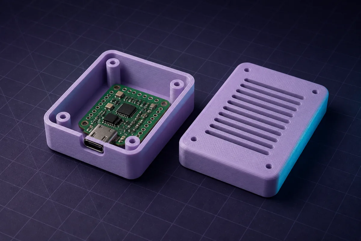
Which ESP32 do you have?
"ESP32 dev board" covers at least a dozen outlines. Measure yours; these are the common ones.
| Board | Outline | Pins | USB | Holes |
|---|---|---|---|---|
| ESP32 DevKitC V4 (38 pin) | 55 x 28 mm | 2 x 19, rows 25.4 mm apart | Micro-B | None |
| ESP32 DevKit V1 (DOIT, 30 pin) | 52 x 28 mm | 2 x 15, rows 25.4 mm apart | Micro-B | None |
| ESP32-S3 DevKitC-1 | 63 x 25.5 mm | 2 x 22 | 2 x USB-C | None |
| ESP32-C3 SuperMini | 22.5 x 18 mm | 2 x 8 | USB-C | None |
| ESP32-S3 SuperMini | 22.5 x 18 mm | 2 x 8 | USB-C | None |
| Wemos Lolin32 Lite | 50 x 25.4 mm | 2 x 13 | Micro-B | 2 |
Almost none of them have mounting holes. The case must hold the board another way.
Holding a board with no holes
- Edge rails. Two grooves along the long sides, 1.8 mm wide (board thickness 1.6 mm plus clearance), let the board slide in from one end. The USB end is left open so the connector lands in its cutout. This is the best option for dev boards that get reprogrammed.
- Pin-row channels. If headers are soldered, two channels in the base capture the pin rows, 25.4 mm apart on most ESP32 boards. Pins act as feet.
- Clip corners. Four small hooks over the board corners. Works, but the board must be pressed in past the hooks.
Ask for the one you want; rails are the default when you say the board has no holes.
Antenna and heat
The PCB antenna sits at one short end. Keep 3 mm of air around it and do not put a wall right against it; 2 mm of PLA is fine. The module gets warm under WiFi load: six 2 x 10 mm slots on each long side keep it in check.
The prompt
Add-ons by chat
- "Add a 5.5 mm hole in the lid above the on-board LED" (say where it is: the DevKitC LED sits near the USB end)
- "Add a 6.5 mm hole for a reset button on the USB side"
- "Add a 22 x 12 mm window for a 0.96 inch OLED on the lid"
- "Add a PG7 gland hole on the far short side for the sensor cable"
- "Add two 4 mm wall-mount slots on the back"
SuperMini boards
The ESP32-C3 and S3 SuperMini are 22.5 x 18 mm with a ceramic antenna at one corner. They fit in a 28 x 24 x 12 mm case and make good keychain sensors. The library has an ESP32-C3 SuperMini case with BME280 vents and an ESP32-S3 SuperMini case with USB-C. For a bigger DevKit there is the ESP32 DevKit project box.
Printing
Base open side up, no supports. Rails print cleanly because they are vertical. Use PETG if the box lives near anything warm; the ESP32 itself does not need it.
Prompts to start from
Open one in the builder, change the numbers to yours, and the model renders in your browser, usually within a minute or two. Keep adjusting in the chat before you print.A project box for an ESP32 DevKitC V4, board 55 x 28 x 1.6 mm with no mounting holes and headers soldered, tallest component 13 mm. Internal edge rails with 0.4 mm clearance, 1.8 mm walls, 18 mm internal height. A 12 x 7 mm micro USB cutout on one short side 3 mm above the floor, 3 mm antenna keep-out on the other short side, six 2 x 10 mm vent slots per long side, sliding dovetail lid.
A case for an ESP32-S3 DevKitC-1, board 63 x 25.5 mm, no holes, two USB-C connectors on one short edge 8 mm apart: edge rails with 0.4 mm clearance, 2 mm walls, 16 mm internal height, two 9 x 4 mm USB-C cutouts, snap-fit lid with hex vents over the module.
A keychain case for an ESP32-C3 SuperMini, board 22.5 x 18 mm, USB-C on one short edge: 1.5 mm walls, 0.3 mm clearance, 8 mm internal height, 9 x 4 mm USB-C cutout, antenna keep-out at the far corner, friction lid and a 5 mm keyring loop.
Questions
With edge rails: two grooves 1.8 mm wide along the long sides that the board slides into with 0.4 mm clearance. The USB end stays open so the connector meets its cutout. Ask for rails and the AI dimensions them from the board size.
PLA and PETG are close to transparent at 2.4 GHz. Keep 3 mm of air around the PCB antenna and avoid metallic filaments. Range drops by a metre or two at most.
Measure it. Boards sold under the same name vary by a few millimetres between makers. Length, width and the distance between the two pin rows are the three numbers that matter.