Designing electronics enclosures with AI: a complete walkthrough
From PCB measurements to a snap-fit box with port cutouts, standoffs and vents, in one chat session. Includes the prompts, the fixes and slicer settings.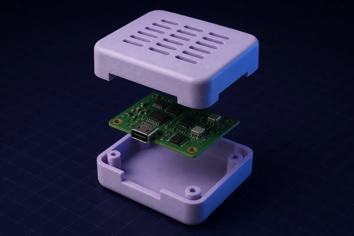
The board
An ESP32 sensor board, 58 x 28 mm, four 2.5 mm mounting holes 3 mm from each corner, USB-C on a short side, a 5 mm LED and a 6 mm push button on the top face, 9 mm tallest component.
Round one
Prompt: "A two-part enclosure for a 58 x 28 mm PCB with 2.5 mm holes 3 mm from each corner, 12 mm internal height, 2 mm walls, snap-fit lid, USB-C cutout centred on one short side 4 mm above the floor, a 5.5 mm LED hole and a 6.5 mm button hole on the lid at 15 mm and 40 mm from the left edge, both centred. Standoffs 3 mm tall with 2.2 mm pins."
Result: base and lid side by side, standoffs in place, cutouts where asked. The AI reported internal dimensions of 60 x 30 mm (1 mm clearance per side).
Round two: the fixes
After a test print, the USB-C cutout was 1 mm too high and the lid clips were tight. Two messages: "lower the USB cutout by 1 mm" and "add 0.1 mm clearance to the snap clips". Both minor: each message was one request (2 credits), and the re-download was free.
Round three: vents and text
"Add a 3 x 5 grid of 2 x 8 mm vent slots on the long sides, and emboss 'SENSOR-01' 1 mm high on the lid." Still a minor change to the same design.
Slicer settings
- 0.2 mm layers, 3 perimeters, 15% infill
- Base open side up, lid face down; no supports
- PETG for outdoor use, PLA indoors
- Brim off; the base has a 0.5 mm chamfer against elephant's foot
What made it work
Coordinates relative to a corner, the fit type for the lid, internal height with component clearance included. The AI did the rest: wall thickness, clip geometry, chamfers.
Variations
Screwed lids with M2.5 pillars, sliding lids for battery access, DIN-rail clips on the back, wall-mount keyholes, or an O-ring groove for weather resistance. Each is a sentence.