Raspberry-Pi-Zero-2-W-Gehäuse, 3D-gedruckt: 65 x 30 mm, die 58 x 23 mm Löcher und ein schlankes Schnappgehäuse
Exakte Zero-2-W-Maße, die Positionen von Mini-HDMI und Micro-USB, Kamerakabel-Austritte, und ein Prompt für ein nur 14 mm hohes Schnappverschluss-Gehäuse.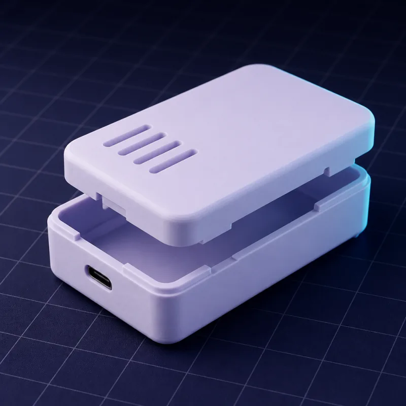
Maße
| Maß | Wert |
|---|---|
| Platinenumriss | 65 x 30 mm, 3 mm Eckenradius |
| Montagelöcher | 4 x 2,75 mm in einem 58 x 23 mm Muster, 3,5 mm von den Kanten |
| Mini-HDMI | Lange Kante, zentriert etwa 12,4 mm von der Ecke |
| Micro-USB (Daten) | Lange Kante, etwa 41,4 mm von derselben Ecke |
| Micro-USB (Strom) | Lange Kante, etwa 54 mm von derselben Ecke |
| microSD | Kurze Kante |
| Kameraanschluss | Gegenüberliegende kurze Kante, 22-poliges FPC |
| GPIO | 40-Pin-Stiftleiste entlang der anderen langen Kante, bei der Standardplatine unbestückt |
| Höchstes Bauteil | Etwa 5 mm unbestückt, 8,5 mm mit eingelöteter Stiftleiste |
Der Zero 2 W und der ursprüngliche Zero W teilen sich diesen Umriss; der Zero 2 W wird wärmer und profitiert von ein paar Lüftungslöchern über dem SoC.
Das schlanke Gehäuse
Ohne Stiftleiste kann das gesamte Gehäuse außen 14 mm hoch sein. Nutz 2,5-mm-Positionierstifte statt Schrauben (die Löcher sind 2,75 mm), und die Platine fällt rein und bleibt unter dem Deckel an Ort und Stelle.
Mit Stiftleiste, einem pHAT oder einer Kamera
- Stiftleiste eingelötet. Füg „12 mm Innenhöhe und ein 52 x 6 mm Schlitz im Deckel über der GPIO-Stiftleiste“ hinzu.
- pHAT obendrauf. Füg „22 mm Innenhöhe, der Deckel über dem pHAT offen“ hinzu.
- Kamera. Füg „ein 17 x 2 mm Schlitz an der kurzen Kante für das Kamerakabel“ hinzu, und wenn die Kamera am Gehäuse montiert wird, „eine 25 x 24 mm Kameramodul-Vertiefung im Deckel mit 2-mm-Löchern in einem 21 x 12,5 mm Muster“.
Wo ein Zero landet
Hinter einem Fernseher, in einer Retro-Handheld-Konsole, in einem Vogelhaus, auf einem 3D-Drucker als OctoPrint-Host. Jeder will eine andere Befestigung: einen Gurtschlitz, ein Lanyard-Loch, zwei Schlüssellöcher, ein 1/4-20-Stativgewinde. Nenn die Befestigung, und sie wird Teil des Gehäuses.
Bibliotheksteil
Das schlanke Schnappverschluss-Gehäuse für den Pi Zero 2 W öffnet sich vorausgefüllt, GPIO-Schlitz inklusive.
Prompts to start from
Open one in the builder, change the numbers to yours, and the model renders in seconds. Keep adjusting in the chat before you print.A slim two-part snap-fit case for a Raspberry Pi Zero 2 W, board 65 x 30 mm with four 2.75 mm holes on a 58 x 23 mm pattern 3.5 mm from the edges. 2.5 mm locating pegs, 1.6 mm walls, 0.5 mm clearance, 9 mm internal height. Cutouts on the long edge for mini HDMI at 12.4 mm and micro USB at 41.4 and 54 mm from the corner, a microSD slot on the short edge, 2 mm vent holes in the lid over the SoC. Outer size about 70 x 35 x 14 mm.
A Raspberry Pi Zero 2 W camera case: board 65 x 30 mm on 2.5 mm pegs at 58 x 23 mm, 12 mm internal height, a 17 x 2 mm ribbon slot on the short edge, a Camera Module 3 recess on the front face (25 x 24 mm, 2 mm holes on 21 x 12.5 mm) with an 9 mm lens hole, and a 1/4-20 tripod thread boss underneath.
A Pi Zero 2 W case with 22 mm internal height for a pHAT, standoffs with 2.5 mm holes on 58 x 23 mm, the lid open above the pHAT, mini HDMI and dual micro USB cutouts, and two 4 mm keyhole slots on the back 40 mm apart.
Questions
Ja, Umriss, Löcher und Anschlüsse sind identisch. Der Zero 2 W wird wärmer, füg also ein paar Lüftungslöcher über dem Prozessor hinzu.
Ja. Verlang eine Kameramodul-Vertiefung im Deckel oder an der Vorderseite mit dem 21 x 12,5 mm Lochmuster des Moduls und einem Kabelschlitz. Das Camera Module 3 ist 25 x 24 mm.
Stifte für ein schlankes Gehäuse, das selten geöffnet wird: 2,5-mm-Stifte in den 2,75-mm-Löchern positionieren die Platine, und der Deckel hält sie unten. Schrauben (M2.5 in 4-mm-Abstandshalter), wenn das Gehäuse kopfüber montiert wird oder Erschütterungen abbekommt.